Part 1 of this article described the Root Protection Area (RPA) and how its size and shape is calculated.
Part 2 explained how the wrong sort of development can harm trees and what the likely consequences are for the developer.
Part 3 will set out a construction methodology to allow development to occur within the RPA of trees. http://s922587449.websitehome.co.uk/2017/11/02/constructing-buildings-within-root-protection-area-rpa/
I explained within Part 2 how tree rooting zones (the volume of soil exploited by a tree’s roots) can be harmed by soil compaction. In a nutshell, soil compaction leads to the soil becoming impermeable to the passage of rainwater and air from above, whilst preventing harmful gasses produced by soil micro-organisms from escaping from the soil into the atmosphere, both of which is likely to result in unsuitable and possibly hostile conditions for tree root growth. Soil compaction is most obvious on construction sites, where heavy plant and other site traffic passes and re-passes over soiled areas resulting in the soil becoming compressed. It is also easy to spot soil compaction on informal pathways where the vegetation has been worn away leaving either a wet puddle ridden winter footpath or a hard-baked summer footpath. Compaction though, can also occur at greater depths below the soil surface. Vibrations from busy roads or heavy plant can cause sub-soil compaction, which although cannot be seen, will impact on trees and micro-organisms all the same. Soil compaction may also result in the pores between the soil particles becoming reduced in size, thereby further reducing the ability of tree roots and soil micro-organisms to flourish. Longer term compaction will often lead to the underlying soil becoming anaerobic and therefore toxic to most tree roots and soil organisms. http://s922587449.websitehome.co.uk/2019/01/30/constructing-buildings-within-the-root-protection-area-of-trees-part-2/
The construction of buildings often produces the same result as soil compaction. Putting aside the cutting of tree roots to accommodate strip or ground beam foundations, the actual footprint of the building often creates the same soil conditions as soil compaction we see on a building site. The building will usually prevent rainwater and air from passing through the soil and will also prevent soil gasses from escaping into the atmosphere, thereby resulting in anaerobic conditions hostile to tree roots and micro-organisms.
It is possible though, to construct a building within the tree’s rooting zone and even within the tree’s RPA without causing harm to the tree’s roots or the tree’s physiology. Open Spaces first developed the ‘Pile and Void’ methodology approximately 10 years ago to allow a double garage to be built within the RPA of a large mature pine tree. Since then, we have gained planning permission for numerous residential houses, house extensions, garages etc. employing the pile and void methodology.
One point I must make though, is that the Pile and Void methodology is concerned with finding a solution for construction within a tree’s RPA without harming roots. It does not provide a methodology for construction within the branch spread of a tree. Even if the pile and void methodology is acceptable to the Local Planning Authority, the proposed development may be refused on the grounds of harm to the tree’s present or future crown. I can almost hear the moans and groans …. what’s the point of the pile and void methodology if the proposed development is thwarted by the tree’s crown? Well, many trees have high crowns, such as pine trees which may tower above a single, or two-story property, and many RPAs are greater in radius than the tree’s crown. The pile and void methodology is not a panacea to allow development within the tree’s RPA, but in many situations, it will make development possible.
I think we now need to go back to the planning system whereby the LPA require a range of information to accompany a planning application. One set of documents relate to trees and may include a report setting out the findings of the tree survey, the Arboricultural Impact Assessment and Arboricultural Method Statements. In addition, a Tree Protection Plan is likely to be required, which sets out the location of tree protection barriers and temporary ground protection. These documents are described within the British Standard which is normally relied on by Tree Officers when recommending development for approval or refusal. The relevant British Standard is BS 5837:2012 Trees in relation to design, demolition and construction – Recommendations. This rather chunky and expensive document is usually at the core of most decisions relating to trees and development. Its purpose is to enable a systematic approach when surveying trees on potential development sites, setting out which trees should be considered for retention and providing recommendations to allow development without causing harm to trees via suitable construction methodology. While there is no specific section within the Standard which discusses pile and void, the methodology recommended by Open Spaces does comply with the recommendations as set out within the Standard.
It was not too long ago that piles were inserted into the ground using a drop hammer or pneumatic system. This required the piling rig to sit above the pile to be inserted into the ground and a heavy weight dropped onto the end of the pile forcing it into the ground. This is an efficient and simple method but where piles were required beneath the canopy of a tree, the rig fully extended could cause serious damage to the tree’s crown. The drop hammer system was therefore generally frowned upon by council Tree Officers and Arboricultural Consultants alike. Nowadays, the drop hammer system is used for multi-story buildings or where soils have particular characteristics.
There are now other methods of inserting piles into the ground. Two methods are described below. Please note though, this is not a blog about the many types of piles or how to impress an Engineer with my knowledge of the different types of piles, which, as it happens, is quite limited. I will leave the intricacies of pile engineering to the Engineer and I strongly suggest that you do too.
1) Pile and Void using bored concrete mini or micro piles.
The project Engineer will need to produce plans to show the size and location of each concrete pile and sections to show how deep the pile will be situated within the ground and how the pile is fixed to the rest of the building. The piles are also called mini or micro piles and are usually between 100 – 300mm diameter.
Prior to the excavation of the pile shafts, the area of ground situated within the Root Protection Area should be covered with suitable ground protection to prevent soil compaction or soil contamination. The various types of ground protection are set out within the British Standard but is likely to include made for purpose interlinked mats, capable of supporting the piling rig and any associated vehicle.
Cylindrical pile shafts are created either by using an augur, attached to a trailer or set on its own mobile rig. The augur isn’t very large and will not impact overhead branches. Once the shafts are excavated, usually a thin-walled steel pipe is inserted into the shaft and steel bars (rebar) inserted, wet concrete is then poured into the shaft. The Engineer mat specify that the steel pipe is not needed or may specify pre-formed piles. If using wet concrete, the upper 600mm of the shaft should be lined with an impermeable material to prevent any wet concrete leaching into the surrounding soil and causing harm to tree roots and soil organisms.
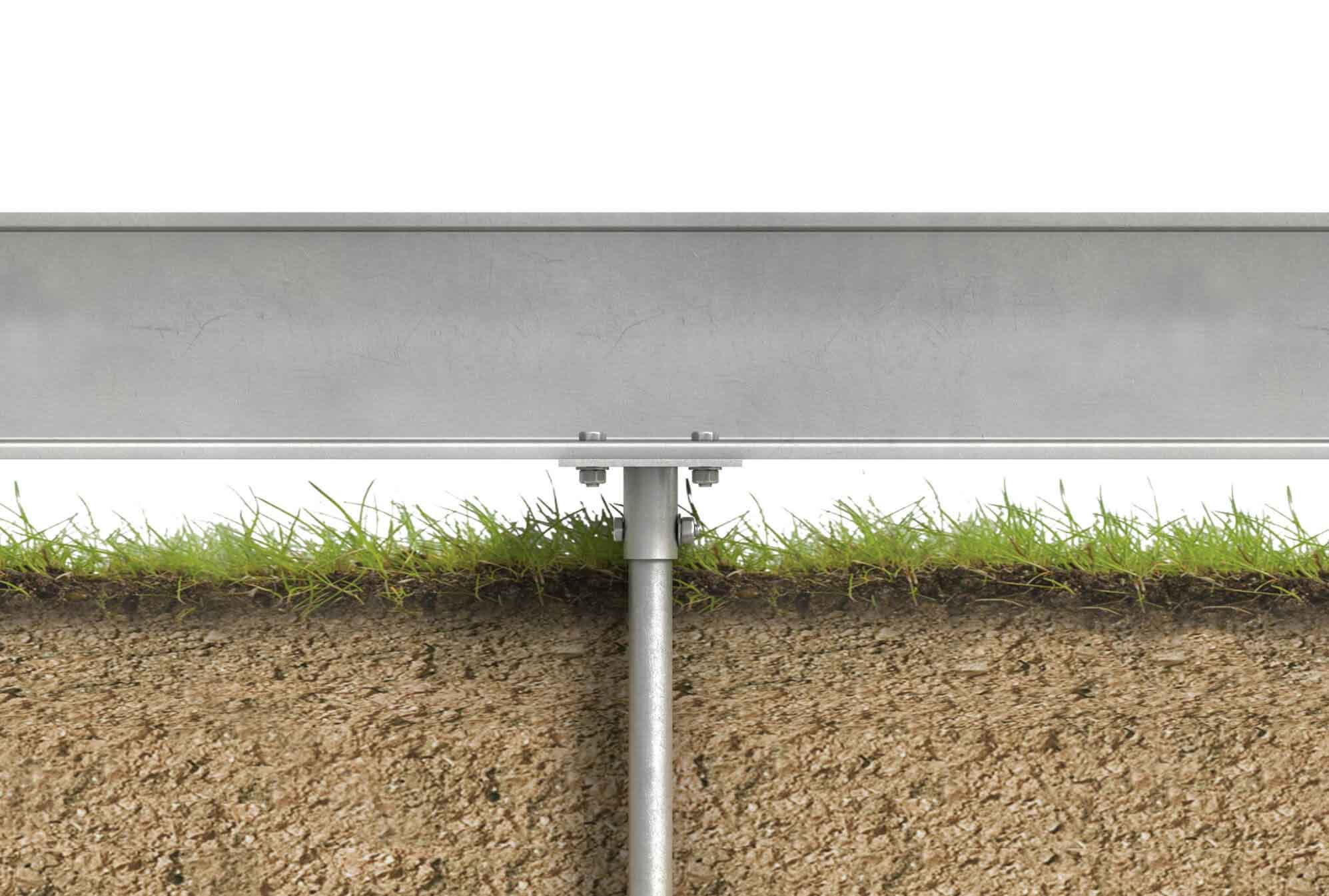
The upper part of each pile remains sticking out of the ground. A concrete ring beam is then cast onto these pile ends to tie the piles together and to create a rigid structure to build the rest of the building onto. It is essential that when the concrete ring beam is cast, no part of it is in contact with the underlying soil. There must be a minimum gap of 25mm beneath the whole of the ring beam to allow for air and water to pass into and out of the soil within the building’s footprint and therefore maintain aerobic soil conditions.
Once the ring beam and any internal beams are in place, it essential that any compaction caused by the construction work is alleviated. This will likely involve bringing in a specialist company who will decompact the ground using a compressed gas decompactor. The decompaction process involves using a small mobile compressor. An operator will remove the ground protection and augur a narrow hole into the ground every square metre or so, to a depth of around 600-750mm. Into this hole, a lance is inserted which is attached to the compressor. A charge of compressed gas (nitrogen normally but could be compressed air) is then released at depth which causes the soil to fracture and loosen, thereby relieving any soil compaction and creating numerous pores and channels for air and water, worms etc to pass through. Once the decompaction is concluded, the newly compacted soil must not be walked over otherwise it will compact again.
A biodegradable clay former can then be laid onto the newly decompacted soil to form a mat. The clay former can be purchased in its own biodegradable bag and looks like a bag of compost but much lighter. The clay former is comprised of clay formed into a lightweight honeycomb structure which can withstand the weight of wet concrete being poured over it without distortion. Once the clay former is in place, a concrete floor can be cast over the clay former. Once the concrete has set, the above ground parts of the building can be constructed. The clay former will disintegrate leaving a void across the whole of the building footprint.
2) Pile and Void using helical screw piles.
As with the bored concrete piles, the project Engineer will need to produce plans and elevations setting out the locations, dimensions and construction methodology of the pile and associated building. The surrounding ground will need to be covered with suitable ground protection.
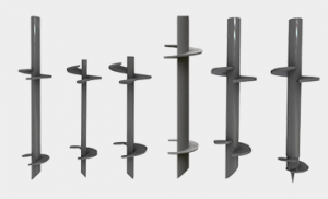
Helical screw piles are usually 100mm diameter with a narrow central steel rod. Attached to this rod are steel vanes, hence the name helical. The image below shows a variety of helical screw piles.

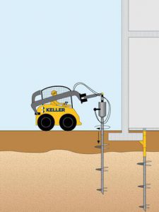
When screwed into the ground, usually by attaching a handheld or trailer mounted augur, the pile will act in the same way as a screw in a wooden joist. Easy to screw in and out but, once inserted, cannot be pulled out except with difficulty. As the screw pile is screwed into the ground, the helical vanes will easily slide past any tree root it encounters.

Once the helical screw piles have been inserted, the upper part of each will remain sticking out of the ground. A steel ring beam can then be attached to these projecting ends. Or, a concrete ring beam can be cast to tie the helical screw piles together. The crucial point here is that, as with the bored concrete piles, once the ring beam is insitu, no part of it should be in contact with the ground. It is essential that there is a gap of a minimum of 25mm beneath the bottom of the ring beam and the soil level. This is to allow air to pass through the soil and gasses from the soil to escape. It will also allow for a watering system to be inserted which will be discussed later.

Once any internal beams steel or concrete are in place, the build can mirror that of the bored concrete piles. There are alternatives to casting the concrete floor over a biodegradable clay former, in that concrete beams could be suspended off the ring beam. This is a cleaner construction methodology as it does not involve clay formers or pouring wet concrete.
Watering systems
When constructing buildings of whatever size, the underlying soil is very likely to dry out or if it remains damp, it must receive moisture by water flowing laterally through the underlying soil. This is also true of buildings constructed using the Pile and Void methodology. It is therefore essential to introduce a suitable watering system beneath the building and preferably a system which mimics the wider rainfall patterns.
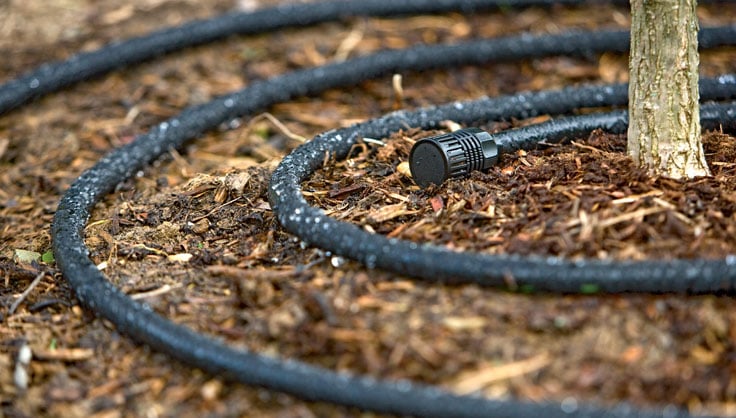
Rainwater is normally slightly acidic pH 6.5 whereas tap water is slightly more alkaline, therefore it would be better for the tree roots to be watered with rainwater. What would also be good, is that the amount of rain which fell onto the building could be transferred to the soil beneath the building and at a time when the surrounding land is also rained upon. It is therefore suggested that the normal rain gutter and down pipes are attached to the building but rather than running into a drain or soakaway, the down pipe is attached to a flexible leaky pipe which lies on top of the soil and within the void beneath the building. The leaky pipe would normally be laid out once the soil decompaction has been completed but before constructing the floor.

The ends of the leaky pipe will require stopping up and the laying pattern may vary but essentially rainwater will fill the leaky pipe and gradually drip (leak) out over the soil.
Finally
This Blog (Parts 1, 2 and 3) has been written to help house owners, builders, developers, Architects and Engineers, in fact everyone and anyone associated with either constructing buildings within the Root Protection Area of trees or those who are thinking of constructing buildings within the Root Protection Area of trees.
Hopefully, this Blog has explained how trees interact with the surrounding soils and how trees and their roots can be harmed, especially during the planning and construction of new developments. I sometimes use the strapline … “Everybody loves trees… as long as they belong to someone else”. This is especially true when it comes to development. To put it another way, we all want everyone else to keep their trees and provide a green leafy environment for us all to enjoy but as soon as one of our own trees gets in the way of our next house or house extension, it becomes a problem tree and fair game in the battle ground that is planning and development.


